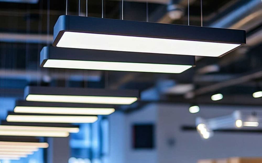
Architectural lighting lives or dies by the strip-and-driver combo.
If you buy from China for multiple markets, the fastest way to reduce risk is to vet against the IEC/CB spine first, then map the same build to US (UL/FCC) and EU/UK (ENEC/CE) variants.
This guide gives you a practical, repeatable checklist focused on LED strips with separate drivers—what to ask for, how to test, and what to reject.
1) Start with the universal spine (IEC/CB)

Ask suppliers for the CB certificate number and the full CB Test Report (CBTR) covering:
- IEC 60598 for luminaires (where applicable)
- IEC 61347 (driver safety)
- IEC 62384 (driver performance)
Verify the certificate on the official IECEE CB Scheme database; confirm:
- model identity
- status
- issuing NCB
- any National Differences noted in the paperwork
Treat CB as your baseline: it doesn’t guarantee local entry, but it proves testing against the international core.
- Quick check: Validate the CB number and scope on the public portal of the IECEE CB Scheme database (official).
- Driver safety: Ensure the driver is certified to the current edition of IEC 61347-2-13 (LED controlgear particular requirements) in addition to IEC 61347-1.
Red flags: screenshots instead of original PDFs; model/code mismatches; expired or withdrawn certificates; CBTR missing clause-by-clause results; National Differences that require additional local testing without evidence of completion.
2) LED components: what proves quality and what to test
- Color consistency and fidelity: Lock the LED bin in the BOM and on the label. Require the strip’s target SDCM (e.g., ≤3) and verify the bin code on both the BOM and incoming samples. Confirm CRI target and R9 if specified.
- LM-80/TM-21 with in-situ temperature: Request the original LM-80 report from the LED package maker and use TM-21 projections only within the 6× rule, based on the LM-80 test duration. Tie the projection to your luminaire’s measured in-situ LED temperature (ISTMT), not a catalog guess. The projection method is defined in IES TM-21 guidance and calculator.
- Photometry sanity check: If you buy as a built linear system, request LM-79 photometry/IES files and check that CCT and flux align with the specified bin and LED count per meter. Small deltas are normal; large gaps often mean bin or current changes.
Practical sample actions: match the LED bin printed on the reel to the BOM; log strip forward voltage per meter at rated current; measure TMP-LED with thermocouples after 30 minutes at full load; keep a photo record of labels and meters for your golden sample file.
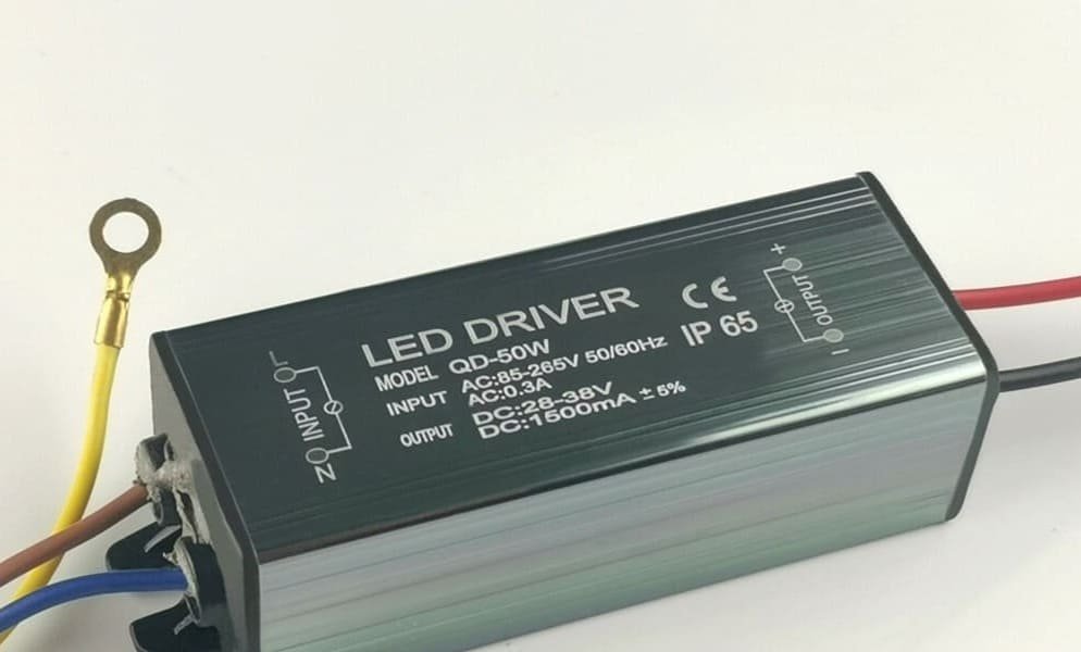
3) Driver selection and reliability (the usual failure source)
Most field issues trace back to the driver: wrong topology, weak derating, poor dimming behavior, or EMI surprises. Start by choosing constant current (CC) or constant voltage (CV) to match the strip’s electrical spec, then check headroom, thermal limits, and control compatibility.
CC vs CV at a glance:
| Criterion | Constant Current (CC) | Constant Voltage (CV) |
|---|---|---|
| Typical strip target | High-power LEDs/boards with defined current | 12/24 V LED strips with onboard resistors/ICs |
| What you control | LED current (brightness) | Supply voltage; strip draws current |
| Pros | Stable current; good for precise lumen control | Simple wiring; supports parallel runs |
| Risks if mismatched | Over/under-driving LEDs; color shift | Overload from long runs; voltage drop dimming |
Key reliability checks:
- Derating and ambient: Load drivers at roughly 70–80% of nameplate at your worst-case ambient (Ta) and install location. Confirm the datasheet’s Tc (case temperature) limit and measure it in situ; stay clear of the limit with margin. Electrolytic capacitors should be 105–125 °C class for long life.
- Lifetime and MTBF: Ask for the method behind any MTBF number (e.g., MIL-HDBK-217 or Telcordia SR-332), assumed case temperature, and component inputs. Treat “50,000 hours” marketing claims without method and conditions as noise.
- Inrush and surge: Gather inrush peak and duration; plan upstream MCB and switching strategy accordingly. For indoor architectural settings, confirm surge immunity appropriate to site conditions; request IEC 61000-4-5 test data.
- Dimming/control: Verify 0–10 V, DALI (IEC 62386), PWM frequency, or phase-cut compatibility as specified. Bench-test for smoothness and minimum level; watch for shimmer or pop-on/off.
4) Flicker acceptance you can repeat
Set acceptance using metrics you can measure the same way every time.
In the EU, temporal light artifacts are checked using PstLM (short-term flicker severity) and SVM (stroboscopic visibility), measured with a calibrated flickermeter as defined in IEC TR 61547-1:2020.
For multi-region projects, keep an internal target that’s tighter than typical requirements so your build travels well.
Suggested practice for architectural interiors:
- Measure PstLM and SVM at 100%, 50%, and about 10% output (or the minimum dim level you plan to use).
- Require low-flicker behavior when dimmed guided by IEEE 1789 recommendations for acceptable modulation at low frequencies. Use the same light sensor, distance, and setup each time to maintain repeatability.
Why this matters: low-frequency PWM or poorly filtered CV drivers often look fine at full power but produce visible modulation at dimmed levels.
5) EMC/EMI sanity checks
Ask for complete EMC test reports—edition numbers, setup photos, plots/tables, verdicts, and ISO/IEC 17025 accreditation.
- EU/UK: Emissions should reference EN 55015/CISPR 15, and immunity should reference EN/IEC 61547. Make sure the emissions report cites the current edition and amendments such as the 2019+A1:2023 update to EN IEC 55015; you can see an official amendment reference in EN IEC 55015:2019/A1:2023. Check EN/IEC 61000-3-2 Class C harmonics when applicable.
- US: For emissions, determine if your configuration is an unintentional radiator under 47 CFR Part 15 and ensure the correct authorization route (SDoC/DoC vs Certification). The rule text and authorization guidance are published in eCFR 47 CFR Part 15.
Watch for: EUT configured without the intended LED load; cable runs shorter than reality; phase-cut dimmers omitted from the setup; plots without limits or uncertainty.
6) Safety mapping by region (concise)
- IEC baseline for multi-region builds: driver safety per IEC 61347-1 and IEC 61347-2-13; driver performance per IEC 62384; luminaire safety per IEC 60598 where a complete linear system is sold. Maintain SELV outputs when required and preserve insulation/creepage in the luminaire wiring.
- US: Verify the model on UL’s official database (Product iQ). Depending on your product, look for UL 8750 (LED equipment), UL 1598 (luminaires), and UL 1310 (Class 2 drivers) where applicable. The search and record types are described on UL’s Product iQ overview.
- EU/UK: For premium assurance, ENEC certificates from a recognized body can complement CE/UKCA. For CE/UKCA, require a Declaration of Conformity with a technical file summarizing safety, EMC, harmonics, Ecodesign, and RoHS documentation.
Remember: check national deviations and local mark rules before you print packaging.
7) Production consistency and shipment readiness
Build quality comes from consistency more than heroics. Freeze a golden sample (strip bin, driver model, dimming curve) and protect it with change control; any swap needs a formal ECN and re-verification. For each lot:
- Run a burn-in at elevated load/temperature appropriate to project risk and record early failures.
- Apply a rational AQL for visual and functional checks; include spot checks of flicker at one or two dim levels on random units.
- Label for traceability: driver model, lot/date codes, compliance marks, and wiring diagrams on cartons. Keep test data with shipment docs.
Receiving checks at your warehouse: verify labels against the PO and golden sample; measure a few units for output current/voltage and case temperature; keep your logs short and consistent so they get done every time.
8) A practical micro-workflow (with disclosure)
Disclosure: Yansourcing is our product.
Here’s a small, repeatable trio of actions you can perform on any architectural strip + driver build:
- Verify CB basics: Use the IECEE CB Scheme database to confirm the certificate status, model identity, and National Differences noted for the driver and, if applicable, the linear luminaire. Save the PDFs to your project file.
- Flicker spot-check: With a calibrated meter following IEC TR 61547-1 methods, capture PstLM/SVM at 100%, 50%, and 10%. If dimmed readings show visible modulation, ask for a driver with higher PWM frequency or better output filtering.
- Derating sanity check: Compare your ambient and enclosure to the driver’s Tc limit. If your measured Tc is within a few degrees of the limit at 80% load, either step up to the next wattage or improve thermal path.
A sourcing/QC partner can help collect the right reports, schedule lab tests, and keep the golden sample and ECN flow under control across suppliers and batches.
9) Next steps
If you’d like a ready-to-use acceptance pack—LED BOM/datasheet checks, 12 driver verifications (including derating and false-rating traps), sample-to-mass production controls, and burn-in/sampling guidance—download our LED/driver QC checklist.
It’s built for multi-region export and designed to be used on every PO.
